
Recently, the new Sava Bridge in Belgrade, Serbia, was examined in cooperation with Niemann Ingenieure GbR. This bridge serves as the main connection between the central area of Belgrade in the east and the district "Novi Beograde" in the west of the river Sava. Following the architectural design of the existing steel arch bridge, the new bridge offers two car lanes in each direction, a streetcar track in both directions and additional sidewalks on both sides.
The bridge consists of a steel structure with a bridge deck made of RC composite material and spans a total length of 420.0 meters, with the largest span being 166.0 meters. The design of the bridge is characterized by two interconnected arches spanning the main section, with the bridge deck suspended from the arches by 2x12 hangers. The bridge deck is also supported by two main longitudinal girders reinforced by internal struts and external cross girders.
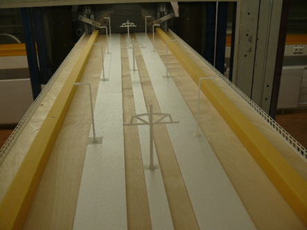
The experimental analysis carried out in the RUB wind tunnel includes the evaluation of aerodynamic forces and aeroelastic phenomena related to key structural elements such as the main girders, bridge arches, hangers and cables. In addition, special attention was paid to the simulation of different traffic scenarios with simultaneous wind action, including streetcar operation and traffic congestion, in order to understand their impact on the bridge design.

Figure 1: Bridge deck cross-section in the RUB wind tunnel (Rights: Niemann Ingenieure GbR)

Figure 2: Wind tunnel tests on bridge section models (Rights: Niemann Ingenieure GbR)

Figure 3: Animation of the new Sava Bridge in the architectural competition (https://www.gradnja.rs/ovako-ce-izgledati-novi-stari-savski-most/)

On 4 February 2024, the first section of the Leverkusen A1 bridge was officially put into operation and opened to traffic. Both the bridge deck and the pylon were analysed in detail in the Bochum boundary layer wind tunnel, including for various construction stages. Both surface pressures and force measurements were carried out on static and dynamic (moving) models in order to determine the wind loads on the structure and its aeroelastic behaviour.

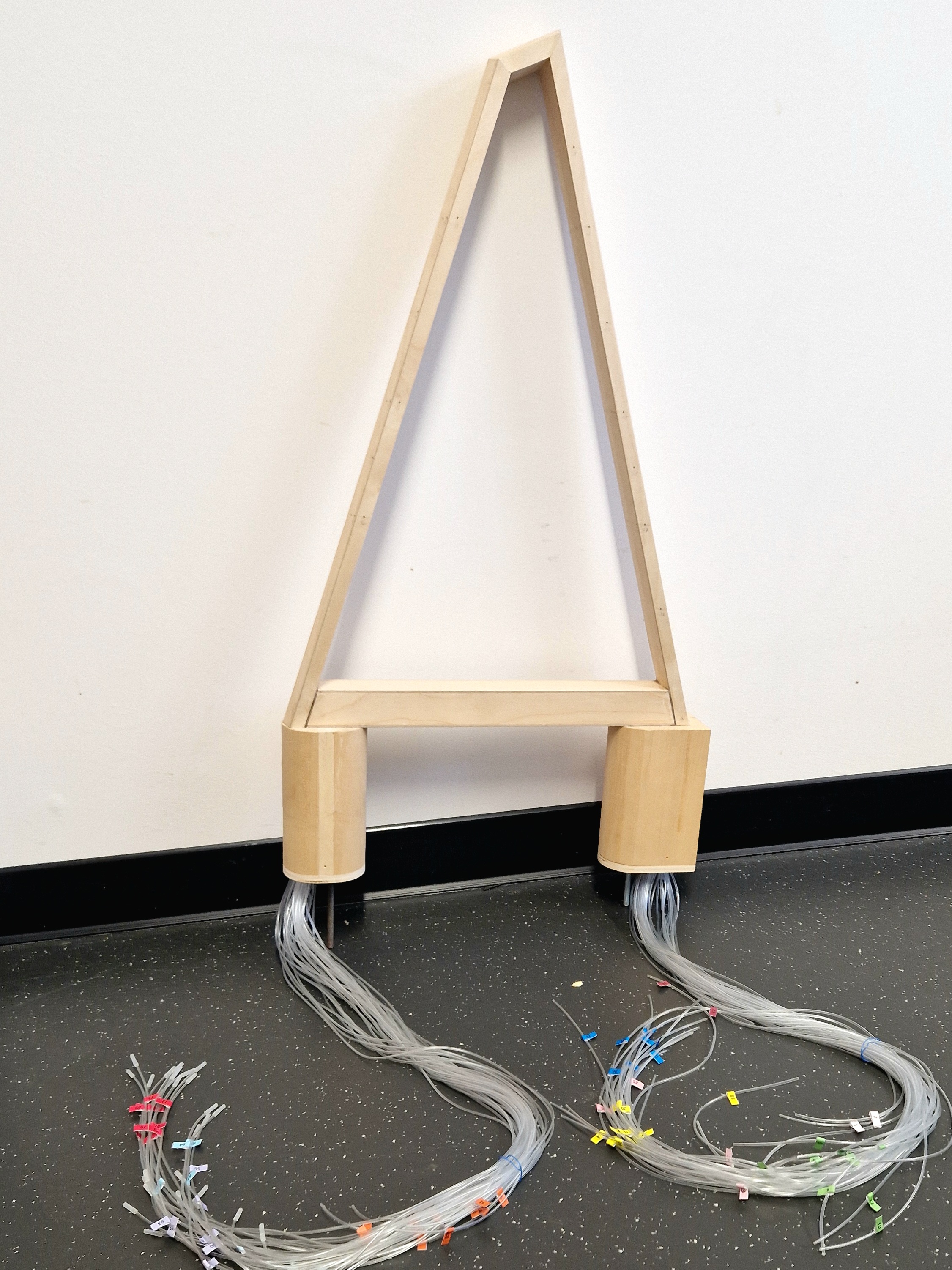
Figure 1: Model of the bridge pylon with the measuring hoses for installation in the wind tunnel.
Youtube option "no-cookies" activated. When playing the video, personal information is transferred only when you are logged-in into a google service.
Video: From minute 7:05 a report on the wind load on the bridge with a visit to the boundary layer wind tunnel at the Ruhr University Bochum.